
I am fortunate enough to have industrial CNC machinery at my disposal, so it was an obvious choice to machine all of the mechanical parts for this machine myself. This blog post gives a brief overview of the process.
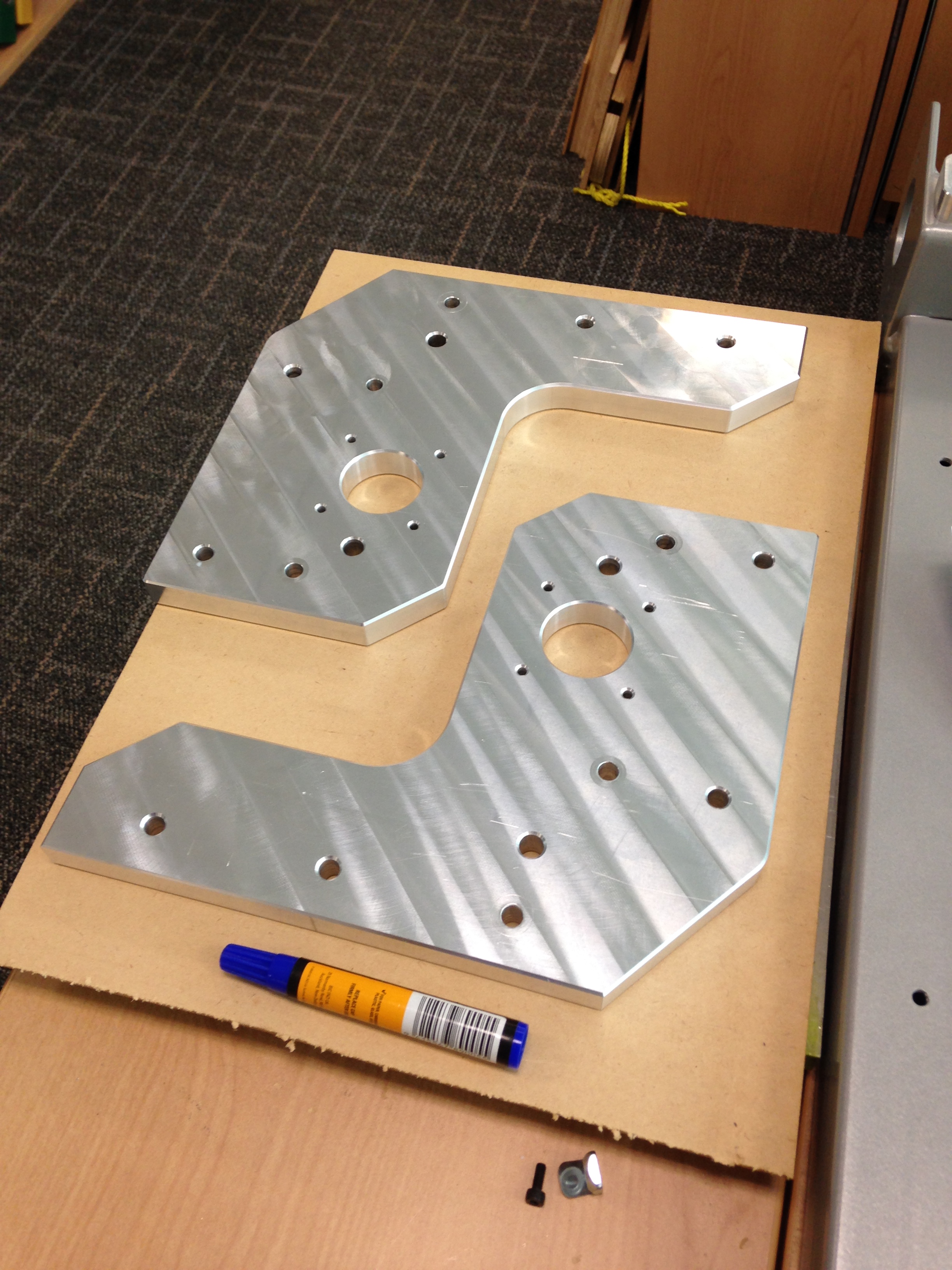
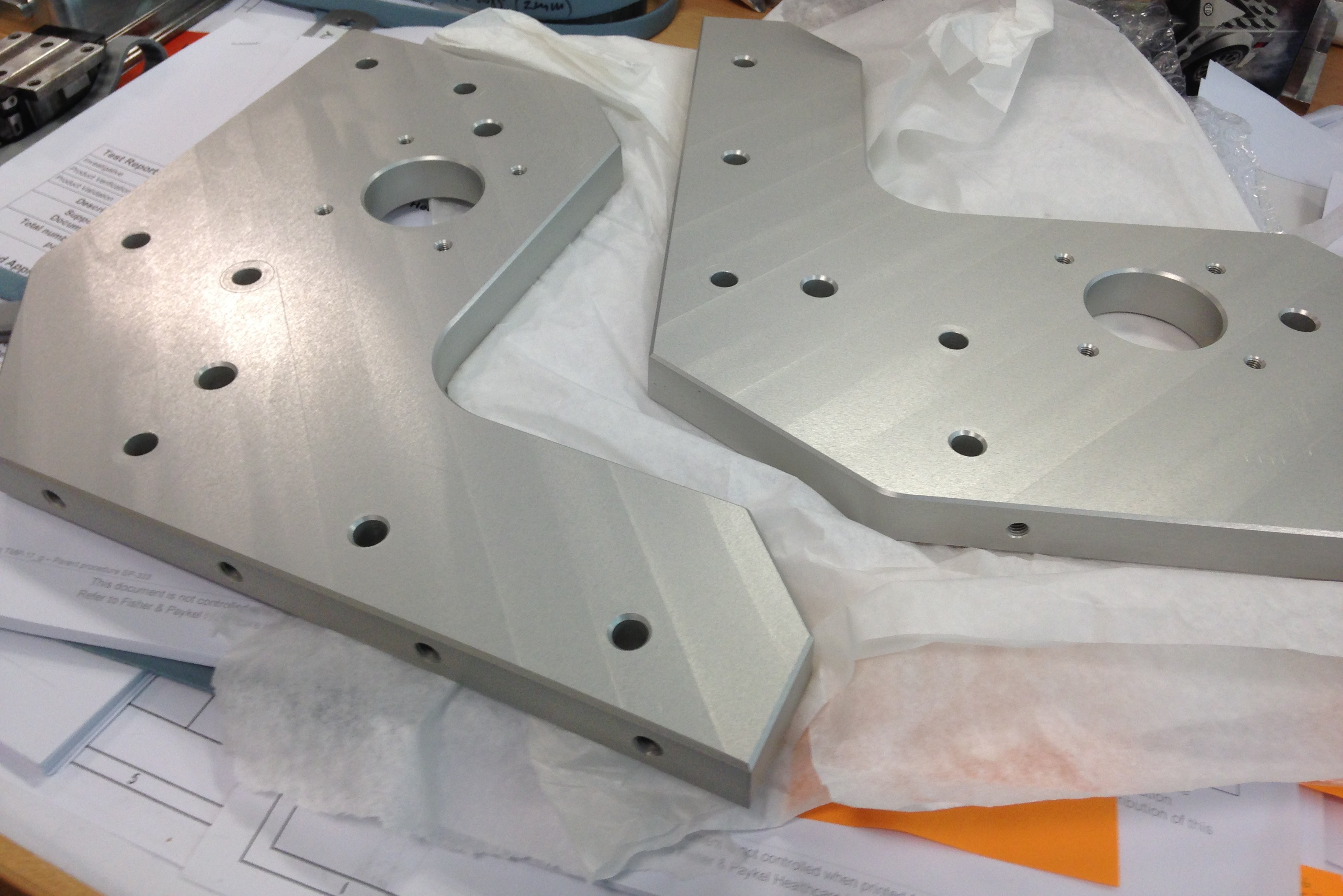
The largest and most challenging components to machine were the Gantry Side Plates. I began with 19 mm 6061 T6 aluminium plate stock and performed a light facing cut on the first side. It was then flipped over, faced once again and drilling/reaming sequences performed.


As we have vises permanently installed on the bed of the machine, it makes it difficult to perform external profiling cuts. My solution was to rough cut the outer profile on a band saw by hand and mount the plates onto a fixture using the 10 mm locating dowel holes I drilled previously. You can see the location dowels in place in the image below, once the bolts were tightened securing the workpiece to the fixture, the dowels were removed and profiling/chamfering of the outside of the component could commence.

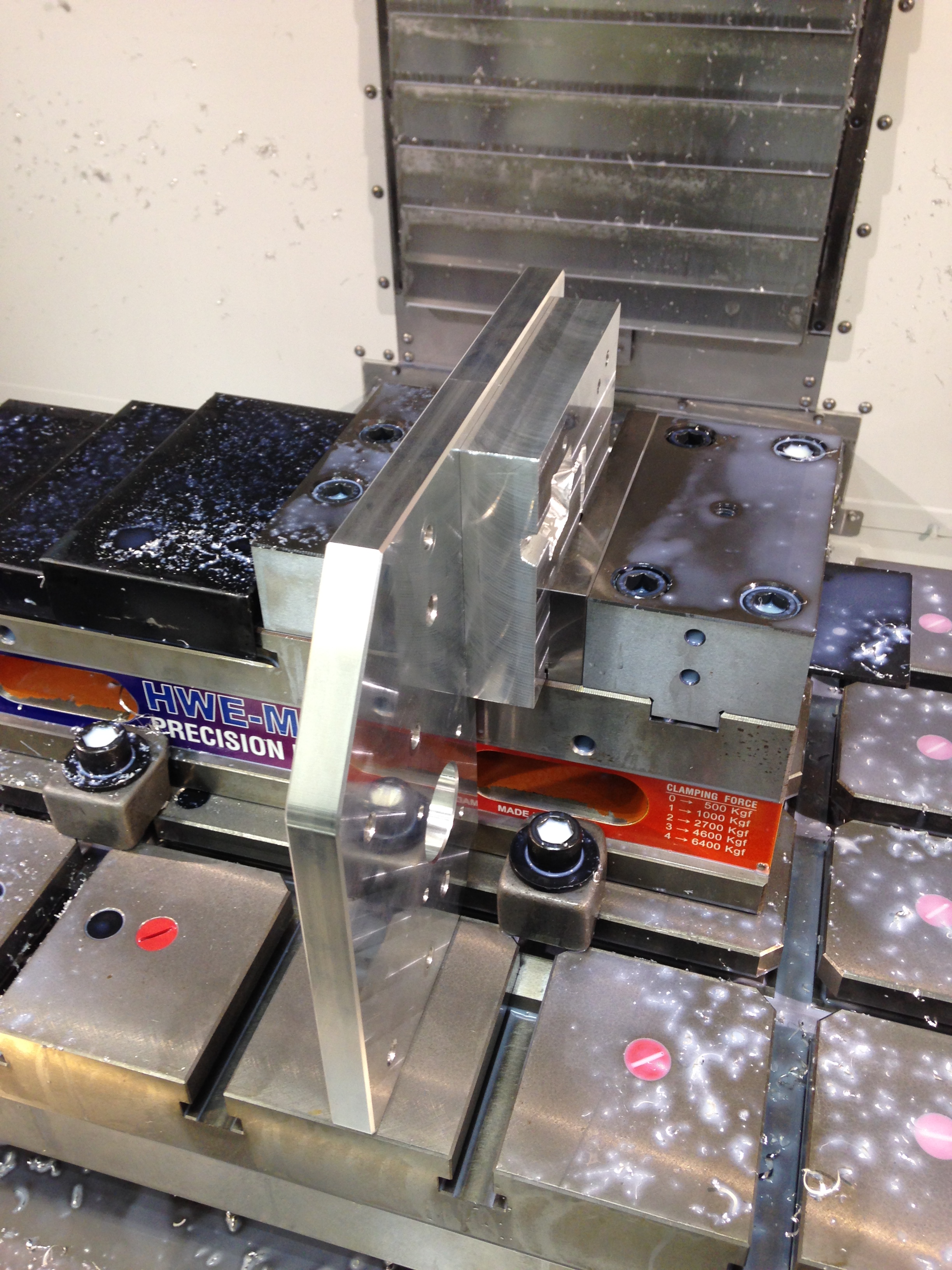
Another challenge which I faced was drilling and tapping into the edges of the Gantry Side Plates, these operations required awkward orientation of the parts in the CNC machine. The holes allow attachment to the main Gantry Platforms and the Gantry Bases, therefore their location and accuracy were critical to the assembly of the machine. This challenge was overcome once again by bolting a fixture to the component. The top edge surface of the component was used to align itself on the bed of the machine whilst the vice firmly held the fixture.

The below images shows a test fitting of the main gantry components.


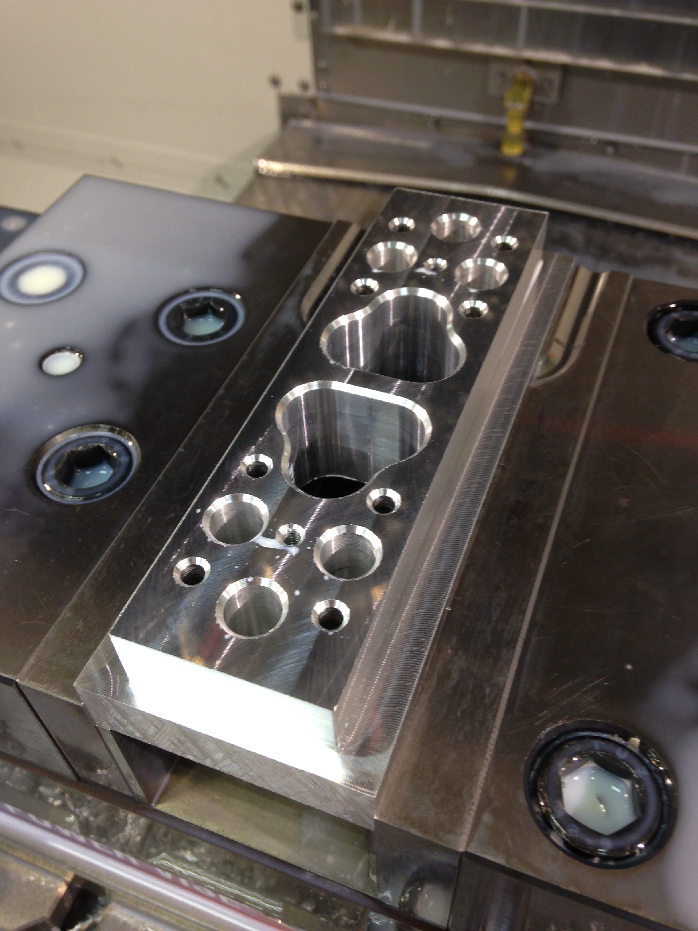
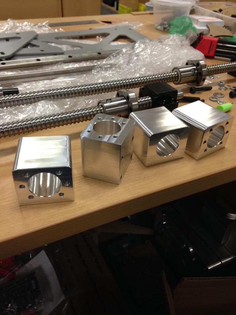
The next task was to begin machining some of the smaller components, ball-screw mounts, ball-nut holders, linear slide end stops, etc.


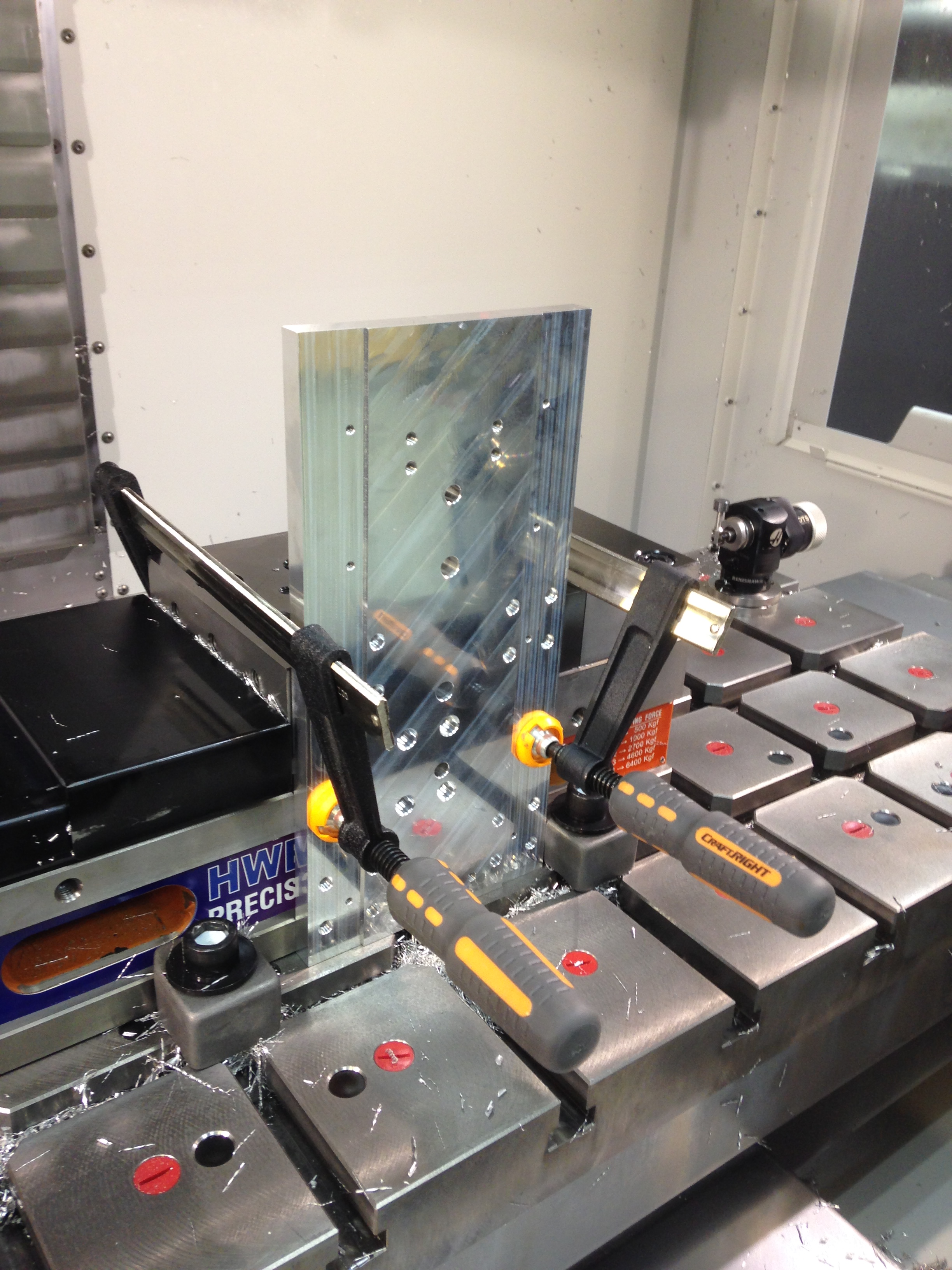
Another interesting machining setup below, using F-clamps to affix the X axis carriage back plate to the side of the vise. The X axis carriage is a tight fit but turned out nicely I think.

Below is an image showing all of the machined components prior to anodising.

I was hesitant about getting the components anodised as it was an extra process which wasn’t necessarily required, but in hindsight I am glad I made the extra effort. They came out with a really nice matte finish and the coating should protect the surface from tarnishing and other marking for many years.

Jeremy, nice work. I want to do the same thing by taking the OX open build and personalize it to my style and needs. How is it working?
LikeLike
Hi Willie, this machine is working well, haven’t had a lot of time to play around with it lately but getting it dialled in slowly! If you look back a bit further on my site you’ll find a post on my first CNC build which was an Openbuilds Ox.
LikeLike
I’m building a machine and am also using open-loop steppers; high torque NEMA 23
Have your steppers ever missed any steps while routing Metal at all?
I’m trying to decide if I should flip the extra nickel and get closed-loop steppers if not; I will be machining hard woods but want the machine to be capable of machining thicker aluminums and steel… (might be going towards more aluminum projects).
LikeLike
I’ve machined wood and aluminum, no steel. Never had any issues with lost steps on my steppers.
Upgrading to Servos would be nice but mainly for the speed and reduced noise. I built this machine almost 9 years ago, at the time closed loop steppers/servos were out of my budget. It seems they have come down a bit in price since then and there is more choice available.
Good luck with your build.
LikeLike
Hi, could you tell me how fast this machine is?
Do you have any problems with 16mm ball screw? Any resonanse or vibration?
I want to build a machine on 1200 x 1000[mm] frame but one of the bounduary condition is to have a G0 feed on 5000-6500[mm/min].
LikeLike
Hi Wojtas, to be honest I haven’t bothered doing much speed testing on my machine, from memory I have the rapids set to 4000m/min, I believe I’ve had them quite a bit higher than that, but set them conservatively for safety reasons. It is mainly used for one off prototyping so high speed machining isn’t a priority. No issues with the 16 mm ball screws, they work well with a machine this size. Anything past 1000m long I think I would start looking at a rack and pinion setup. May I ask why you have set that target?
LikeLike
Hi, as i’am wrote, that is a my bounduary condition. When I start thinking/ preparing to do my project a need some data from where i start. That’s one of them.
Right know i’am developing next concept of my 3D model, because all the time when I see something interesting i want to change on my model. Main issue is to build a router and don’t spend to much money, so all the time I am looking for new low-cost solutions.
In my opinion You had a good idea to built a X-axis “frame” using a aluminum profile. I want to copy that into my model but i don’t understand how You join (useing bolts) aluminium profile and “~25mm vertical plate/sheet” –> i don’t know how to call that part so maybe a call it “WING”
I have a lot of questions, if you want to help me, better will be to sent a email than write over here, what you think?
LikeLike
Hello Jeremy. I am really impressed with the work you have done here and I am curious if you would be interested in working with me to machine a few parts for a machine that I am trying to build. I was very naive when I began and did not realize that I needed a cnc to build a cnc. I am embarrassed to say that I am in way over my head and in the hole way more than if I would have just bought a machine. I can’t give up now for many reasons but I need help. Are you at all interested in helping me? Im not sure what it would cost and I may not be able to afford it but if you are interested in at least taking a look at what I got and we can go from there?
LikeLike
Hi Justin,
Thanks for your message. Send me an email at the address on my contact page and w might be able to work something out.
Cheers
J
LikeLike
Boa tarde sou do Brasil acha que conseguiria Mandar o desenho em tamanho real para rio de janeiro,pode ser a cobrar, papel.de desenho com os buracos e tudo mais , obrigado amigo
LikeLike
Hi Jeremy
Great work! I am very impressed! I am very experienced in TIG welding and I am looking to make a CNC router, But unlike you I don’t have access to a laser cutting machine to cut the parts, I certainly can do the base metal frame and buy the tracks and stepped motors but I can’t do the flanges and other holding parts. BUT, I work a lot with a CAD program (Rhino 5) and certainly can make the file on DXF to be cut by a laser cutting service I use. Would you be willing to give me the drawings of the parts or plans of them, I am willing to pay you for them.
Looking forward to your reply.
Regards
Marcel
LikeLike
Hi Marcel,
Thanks for the message. I have the complete 3D model available for sale on my Etsy site. You can purchase them there and open in Rhino.
https://www.etsy.com/nz/listing/819772173/diy-cnc-router-milling-machine-3d-model?ref=listing_published_alert
Cheers,
Jeremy
LikeLike
Thanks Jeremy
Do your plans includes plans of the metal base? And can the machine be built without the gantry chain, but only with driving screws ?
LikeLike
Hi Marcel,
Yes the model includes the steel base. If you go to the Etsy link you can see a screenshot of the actual 3D model.
Cheers,
J
LikeLike
sorryI just realize what I thought was a cahin is only a electical wire protection
LikeLike
That is correct, it is a “cable chain”, used to manage and protect the cables and coolant tubes.
LikeLike
Hi Jeremy
Thank you so much for your replies.
1-Coolant Tube? I have an air compressor. is that Air from a compressor for the coolant?
2- I am gathering as much information as possible so I am sorry if I ask a lot of questions: I am very good in metal working, machining, welding and working with Rhino, but I am hopeless with the connection of the computer to the machine, that’s the most daunting thing I am apprehensive about. Is there anyone you can recommend who would be able to help possibly in Melbourne. I don’t mind the expense. I need the outlet to buy the hardware and someone to teach me how to connect to the machine and calibrate it. I’ve seen your video but I am not confident on understanding it.
You can contct me on my email address if that is ok with you.
Kind regards
Marcel
LikeLike
salut Jeremy , je suis fascinait par votre model de CNC , j’ai une cnc 6090 depuis 2009 , et maintenant j,ai besoin d’une d’un espace de travail 1500 x 3000 mm , c possible votre plans pour cette dimension .
LikeLike
Hi Samir, I don’t have plans for a machine that big. You could try taking my model and adapting it, it is available on my Etsy store.
LikeLike
I was wondering do you sell any of these
LikeLike
Hi Jeremy
Simplicity is the key of DIY.
Your work is wonderful but it is too complex.
I am involved 36 years on design & manufacturing and admire your view of designing.
Your’s sincere
M. Mastoori
LikeLike