
This project is my take on the ‘Overnight Sensations’, a DIY speaker design by Paul Carmody which has received great praise among the DIY audio community. These speakers have been known to produce amazing sound with surprisingly good bass response, especially for a speaker of this size and cost.
The Overnight Sensations’ driver arrangement consists of the versatile Dayton Audio ND20FA-6 3/4″ neodymium silk dome tweeter and the HiVi B4N 4″ alluminum midbass woofer. Paul has specified a cabinet size of roughly (4.5 liters) and is tuned to 53 Hz using a 6″ long, 1-3/8″ diameter port.
A full kit including cabinets is available from Parts Express, although shipping a heavy package full of timber from USA to New Zealand is horrendously expensive. My solution was to order the components only and cut the cabinets on my own CNC Router as shipping the electronic components alone isn’t nearly as expensive as the full kit. If you are also in this part of the world and would like to purchase a set of flat-packed cabinet panels directly from me, please see the link at the end of this post for more info.
By machining my own cabinets it would also allow me a bit more freedom to explore the aesthetics of the cabinet.
Design
I drew some quick sketches and further explored some concepts in CAD. It was a tough decision between the classic beveled front baffle style and the more modern chamfered all round look. I went for the latter.
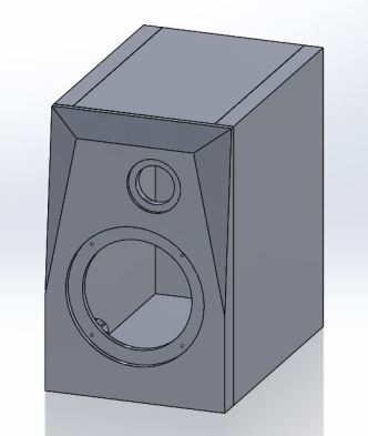
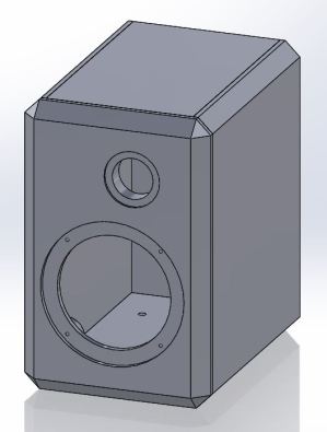
Taking Paul’s original plans which specified either 1/2″ or 3/4″, I adapted the design to the metric system using 16 mm material and modelled it in 3D using Solidworks.
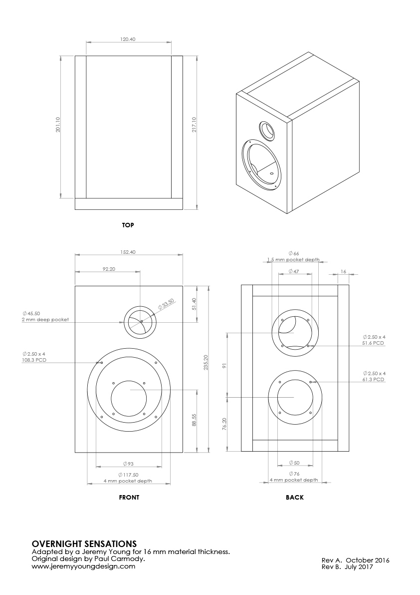
Click here to download a PDF version of this drawing, alternatively here for a complete Solidworks 3D model.
The GIF animation below shows how the panels fit together. Note: the chamfers were to be machined after the panels were glued together and sanded square. This would ensure continuity of the chamfers across the panel joins.
Cabinet Construction
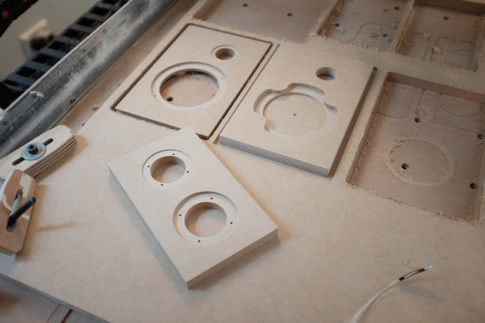
The image below shows the front baffle, which is machined from the front side, flipped over, placed on a locating jig and then driver pockets machined into the rear.
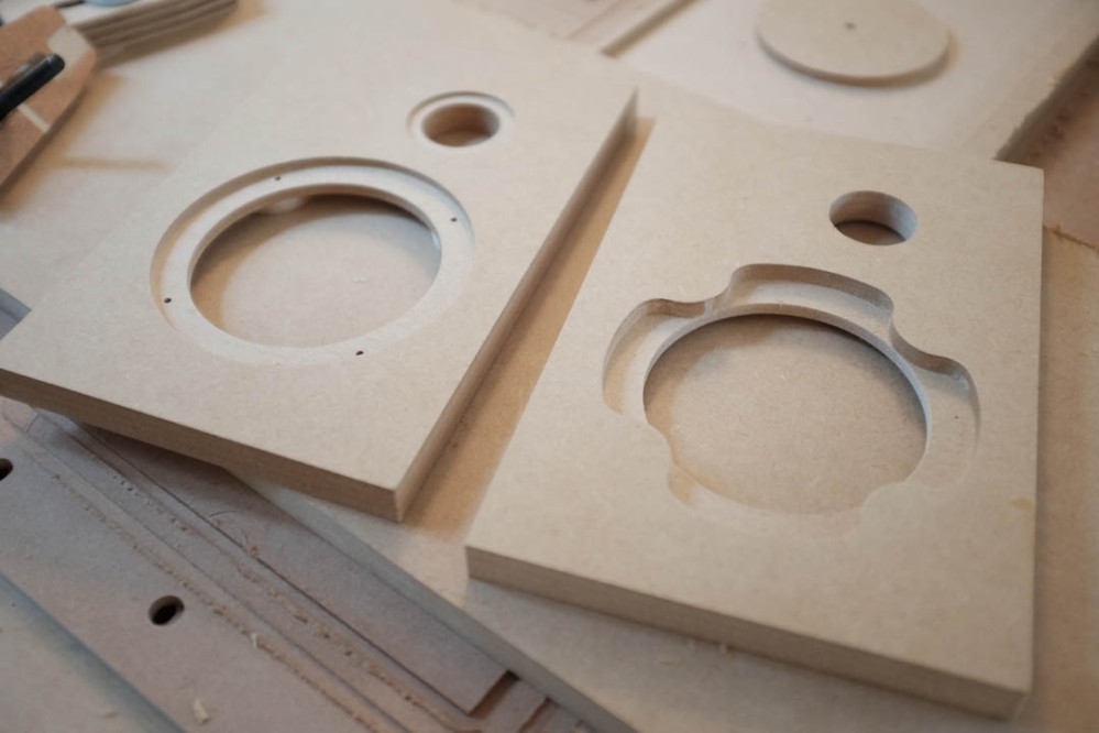
Back panel with recesses and holes drilled for the bass reflex port and binding post cups.
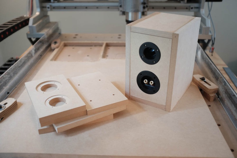
This image shows a partially completed box with the port and binding post cup test fitted.
The video below shows some of the cutting process.
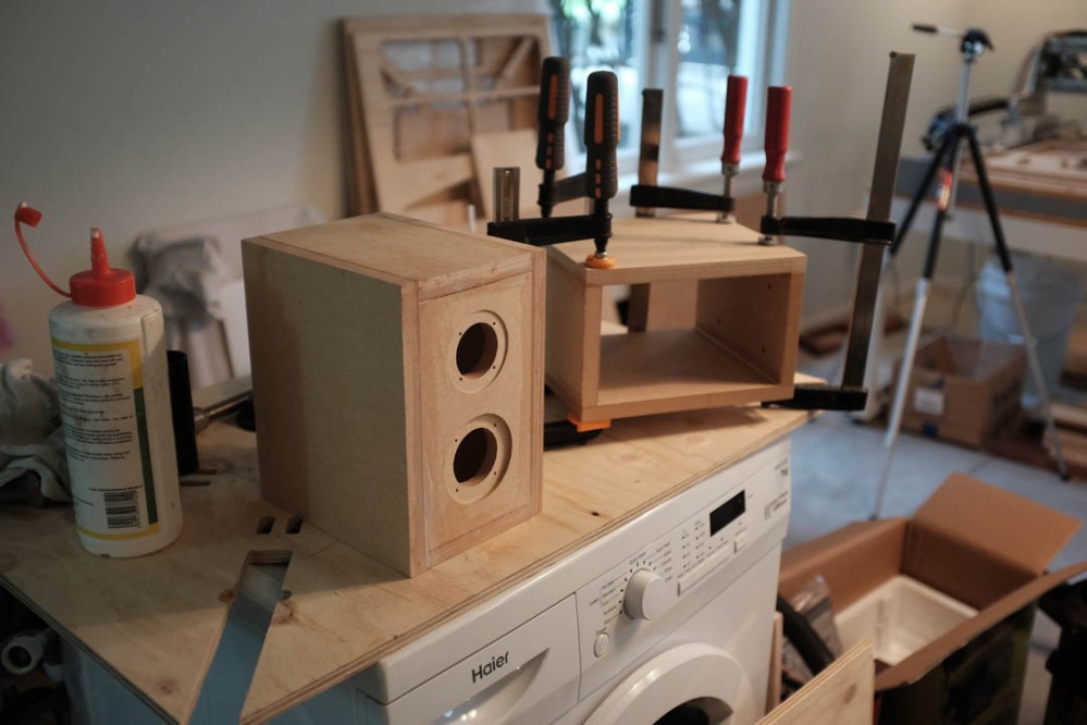
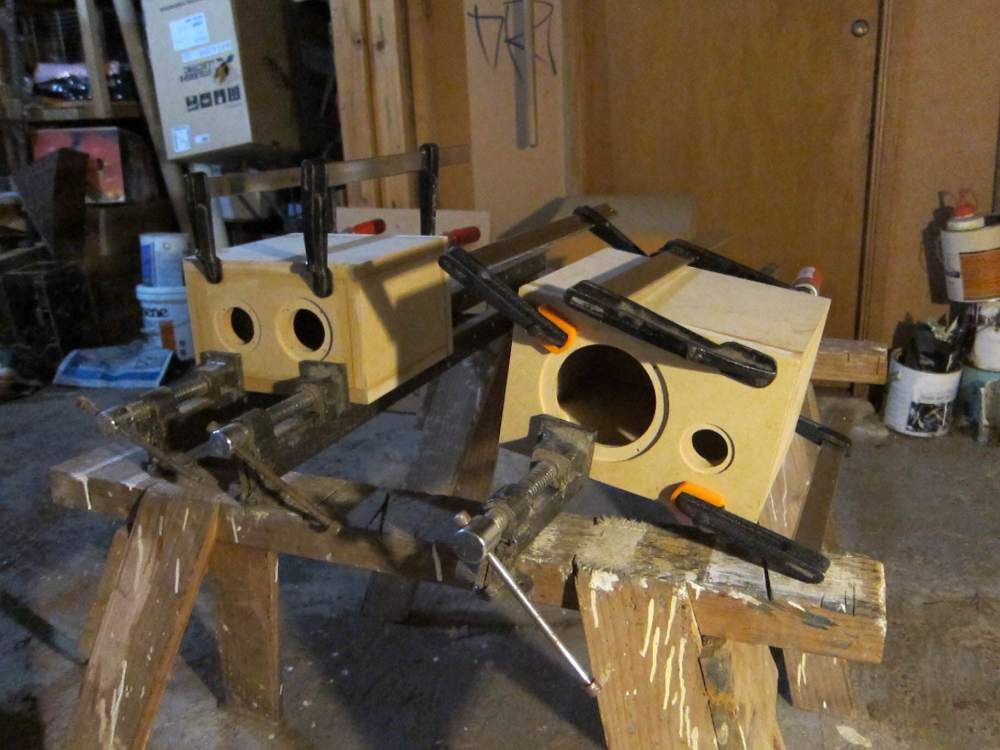
I glued the top, bottom and side panels together in the first step, taking care to keep everything straight and flush on the sides. Ensuring that all the joints were aligned was key to reducing the amount of laborious sanding I would need to do at a later stage. The next step was to glue the inset back panels in. This can actually be combined with the previous step if you have enough clamps and are clever with keeping everything aligned.
The baffles were then glued to the front of the cabinets.
One of the benefits of utilising CNC machinery is the accuracy, everything is perfectly square and accurate. I intentionally cut the front baffle slightly oversize, by roughly 1 mm on each side. Once they were glued to the cabinets I could sand them back to meet the other surfaces. If I hadn’t made this allowance, there is a possibility that a side, or bottom panel would sit ‘proud’, this situation would require a lot of sanding of large surfaces to rectify, which is not ideal.
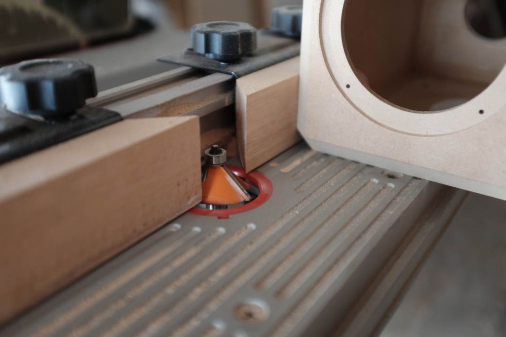
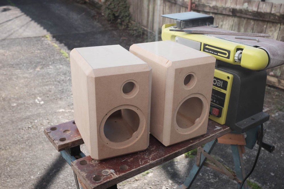
The next step was to cut the large chamfers onto all edges of the cabinet. This could have been done with a hand router but I chose to use a router table for extra stability. A large 45° chamfer bit was used, as seen in the image below.
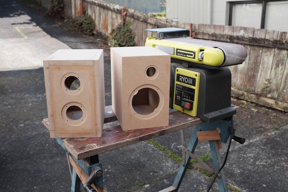
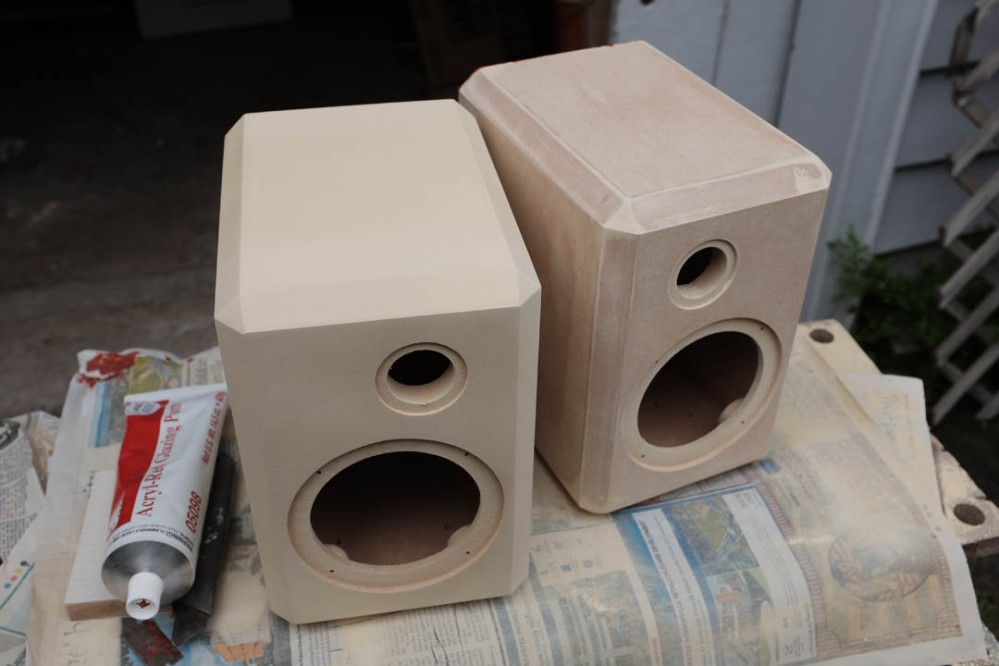
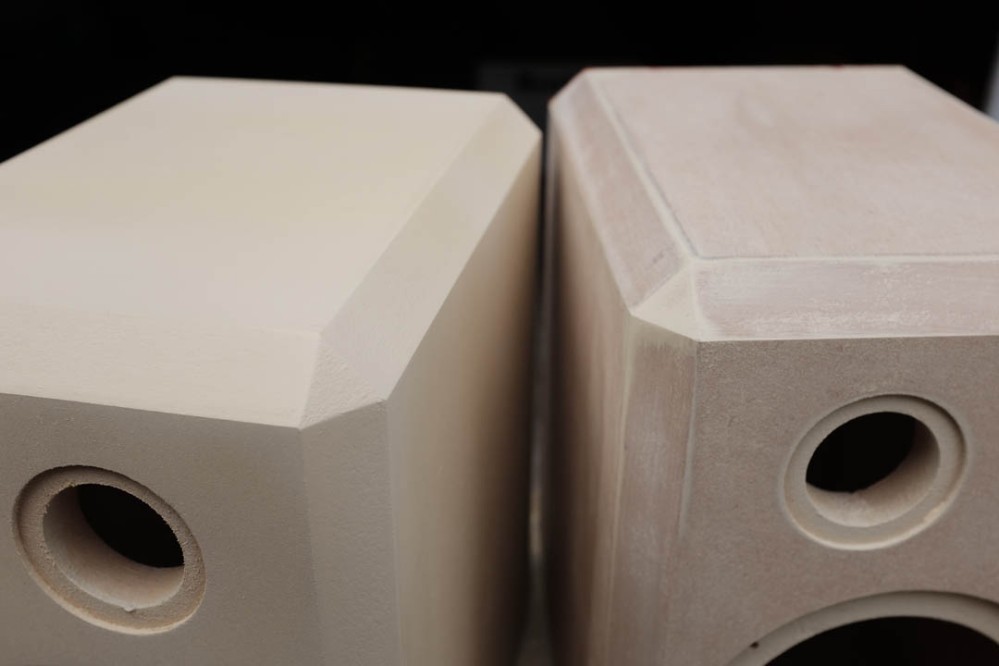
Initially I thought that i’d be able to achieve the small triangular surface on each of the corners using the router bit, but after a test cut I realised this was not the case. The cabinet on the right in the image below has had chamfers cut on all the edges, as you can see I was left with a point on the corners. I attempted to run the router bearing along the adjacent chamfered face, but the result was not a clean triangle shaped face, more of a four sided trapezoid. I resorted to hand shaping the corners using a coarse file and sand paper.
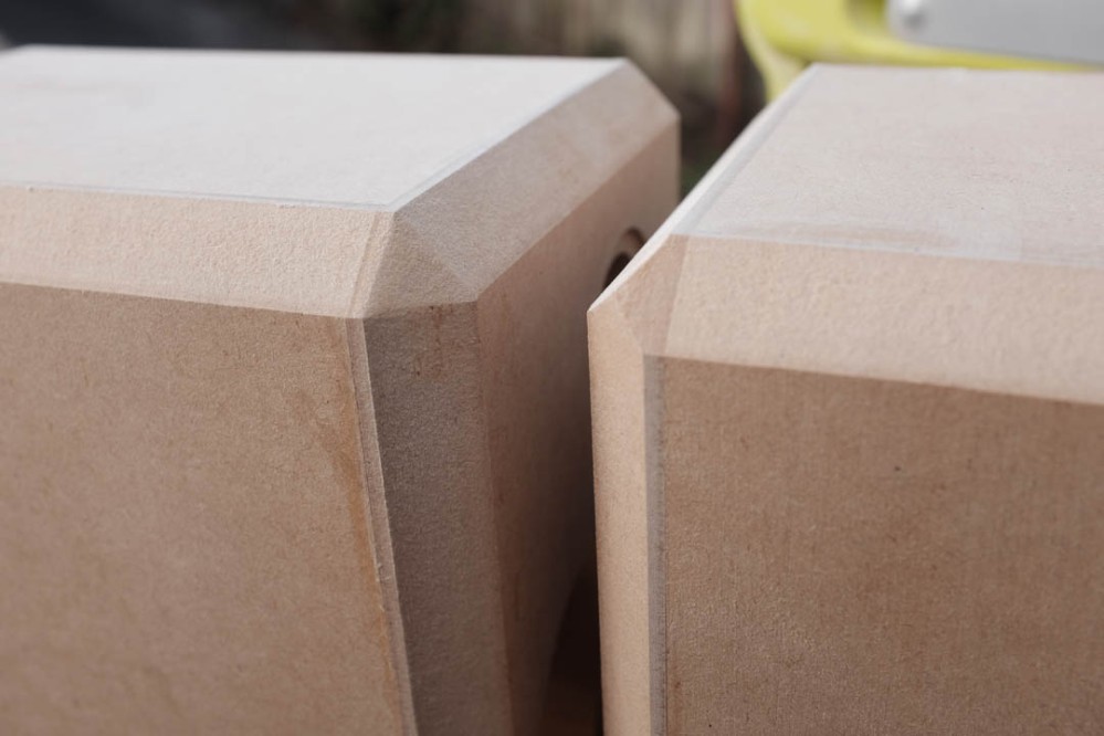
Hand shaped corner (left).
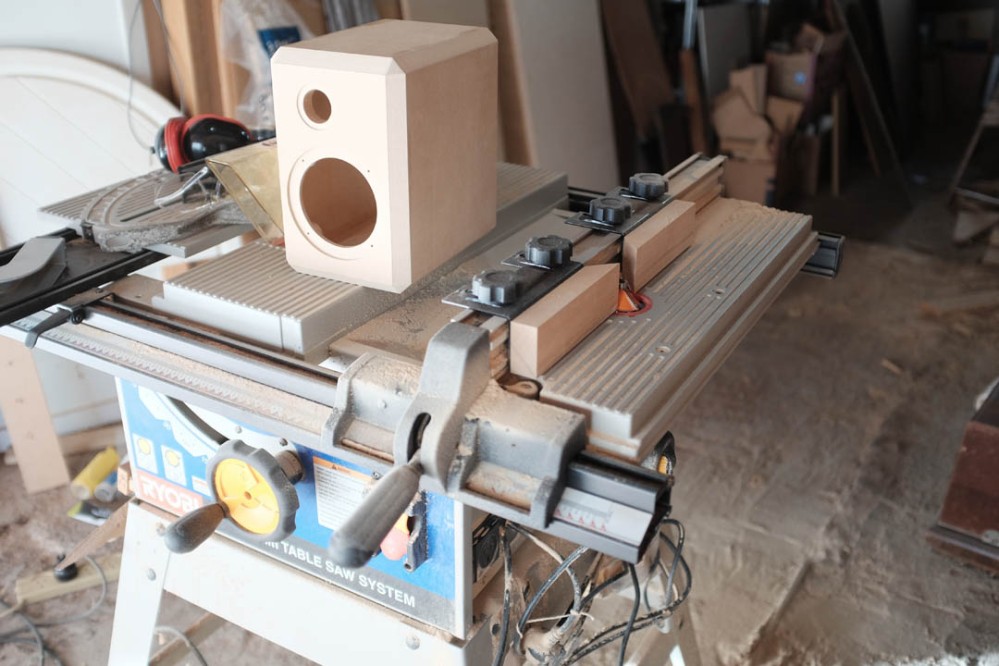
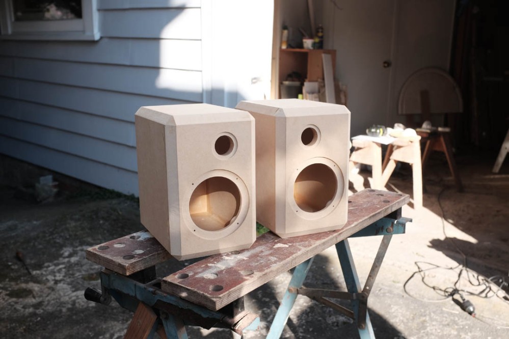
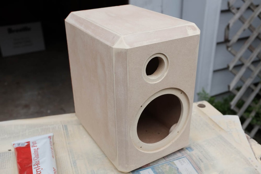
Completed cabinets sanded smooth with 120 grit sand paper and ready for sealing.
Painting
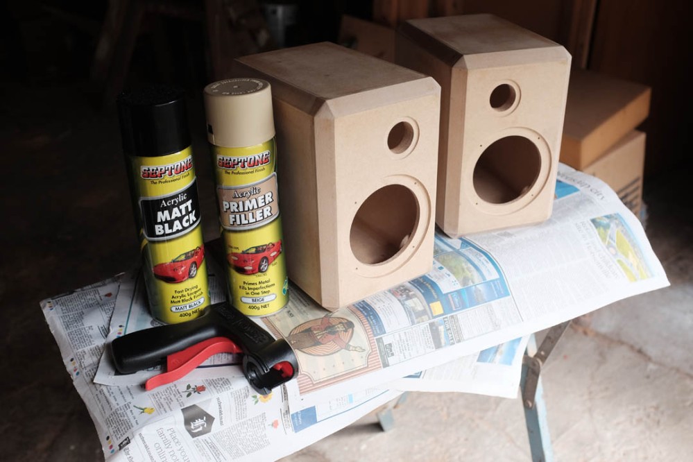
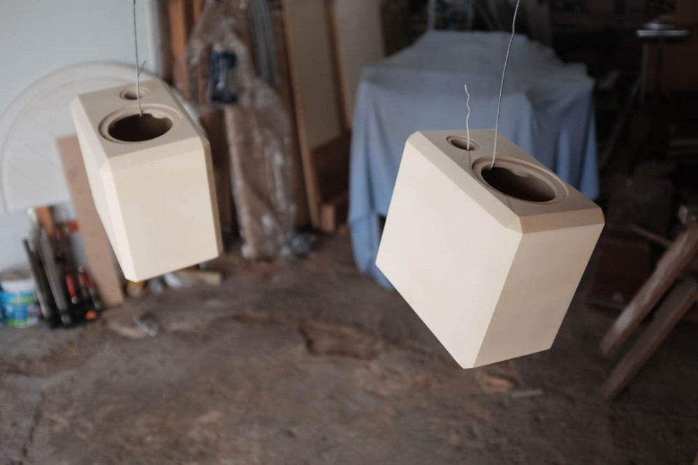
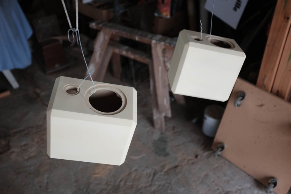
Prior to painting, the MDF needed to be sealed, especially on the edges and machined faces. It is known that if not sealed prior to applying paint, these rough surfaces will suck up large amounts of paint and require many coats to cover. I used a 50/50 mix of water and wood glue, a couple of coats brushed onto all the external surfaces and lightly sanded with 120 grit paper.
This was the first time I had attempted a high quality paint finish. I sought advice from colleagues and a local paint supplier I was advised to use acrylic lacquer aerosols, as they provide a good finish and drying time is significantly shorter than enamel paints. I began spraying with Septone Acrylic Primer Filler.
First coat sanded back with 400 grit, which removed almost all of the primer. I was careful to do all of my sanding using a suitable sized block, this ensures flat surfaces and nice crisp edges.
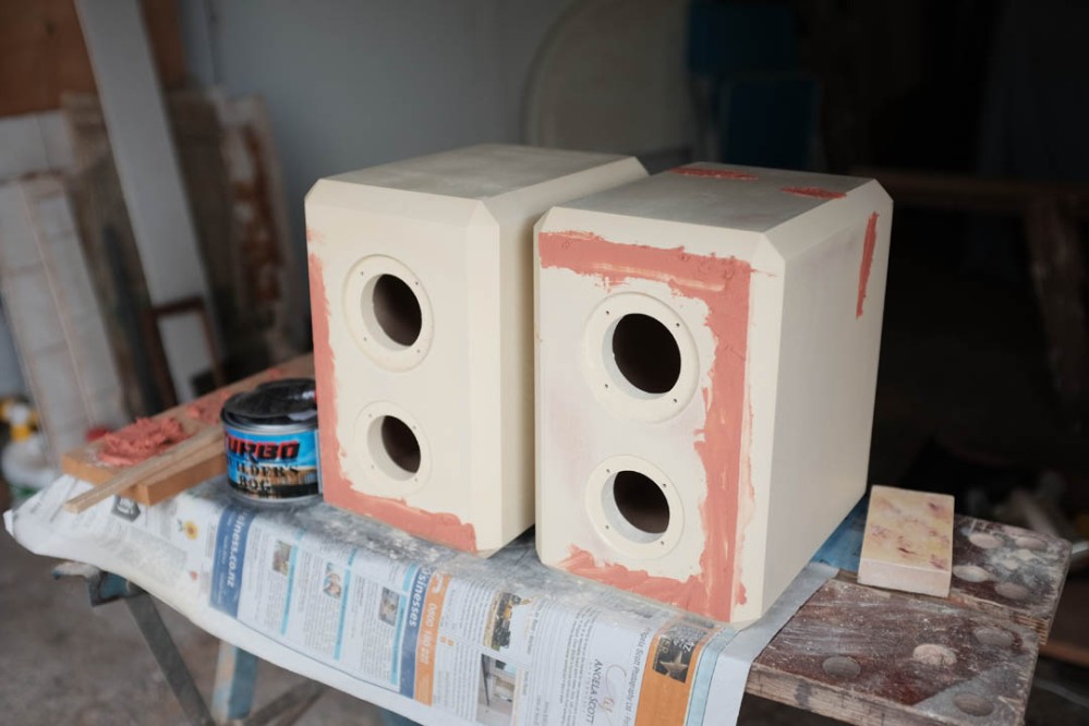
The idea with filler primer is to fill all of the shallow imperfections, once sanded smooth it should result sin a perfectly flat and smooth surface. In reality there are often flaws and imperfections which are too deep to fill with primer. These require the intervention of a filling putty or equivalent product. In my case it was slightly loose fitting inset back panels and a few deeper gouges in the side panels which resulted from over confidence when sanding the baffles flush with the belt sander. I had mixed results with several products and am still not confident that the products I used were going to do the job. I had trouble getting the filler to harden completely but decided to continue anyway.
Once all of the imperfections were remedied and everything was block sanded flat and smooth with 400 grit paper, I was ready to begin my colour coats. I was getting frustrated with the sand paper getting clogged up very quickly, after a fair amount of experimentation I found that sanding in a circular motion rather than in one direction helped alleviate this.
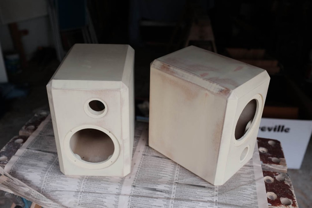
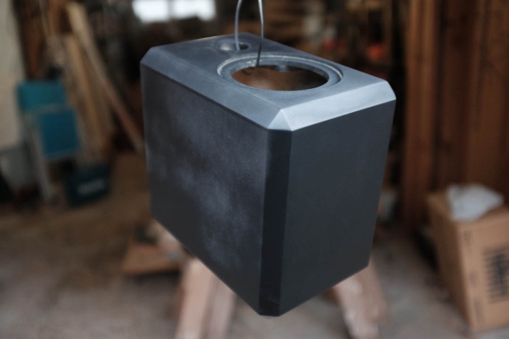
I was keen on a nice flat satin finish and decided to try the Septone Matt Black, also an acrylic lacquer. The image below shows the cabinets fully block sanded with 400 grit and ready for the first colour coat. I also lightly “broke” all the edges by sanding lightly with 400 grit, this allowed the paint to sit nicely around the edges.
The first coat went on quite blotchy and uneven. I think this was a result of my novice skill level and the fact it was the first coat.
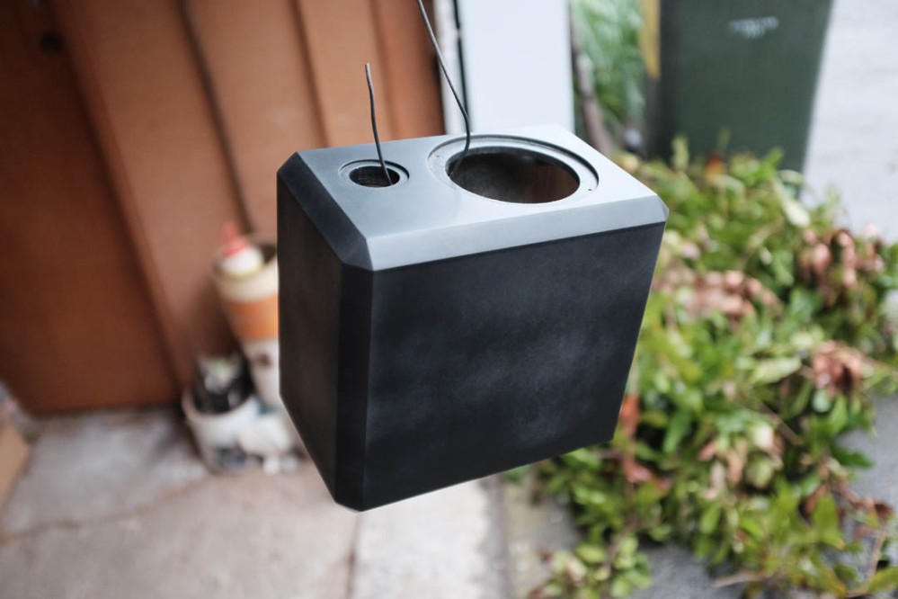
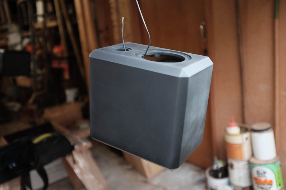
After three coats of matt black I managed to get a very even finish which I was was very happy with. It took me a while to get the hang of efficiently spraying even coats of paint and I it was important to wait for each coat to dry fully before applying another. At one stage I attempted to “go back” and touch up some spots, this proved to be a mistake and I ended up with a blotchy mess. It’s worth noting that I did not sand between the three top coats, I think being a matt finish I was allowed this luxury and it worked out nicely.
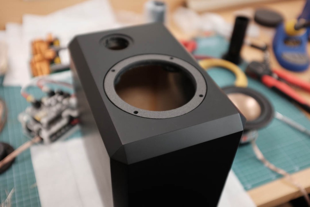
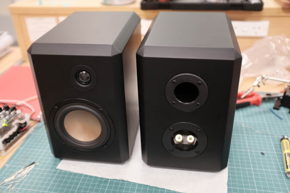
Test fitted the external components.
Electronics Assembly
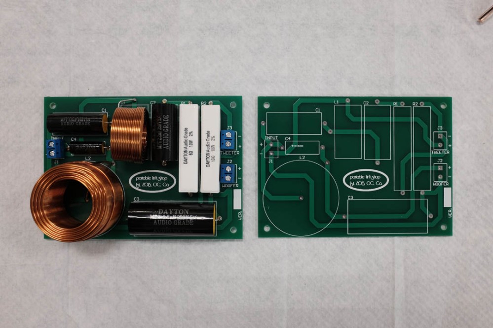
The next step was to build the crossovers, I managed to find a seller (hngo01) on eBay selling custom printed circuit boards for the Overnight Sensations. Purists would argue that a “hard-wired” crossover is far superior when sound quality is concerned but on this occasion I chose to go with the tidier and more easily executed solution.
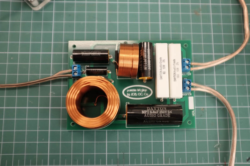
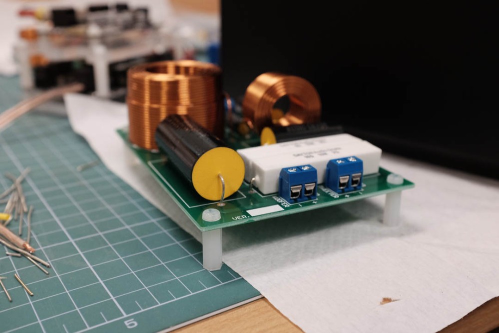
These PCBs were straight forward and very easy to assemble, I soldered everything in and epoxy glued the conductors to the board. One thing I did note is that there was a mistake on the PCB, when compared to the original circuit diagram, capacitors C3 and C4 were swapped. This wasn’t an issue as it was only the labeling on the PCB, the physical circuit was correct. I followed his photo for assembly, these caps are very different in physical dimensions, therefore almost impossible to actually install incorrectly.
I noticed that the leads of the 0.35 mH (L1) inductor looked as if they could easily touch and short-out, so I added some heat shrink insulation around one of the leads.
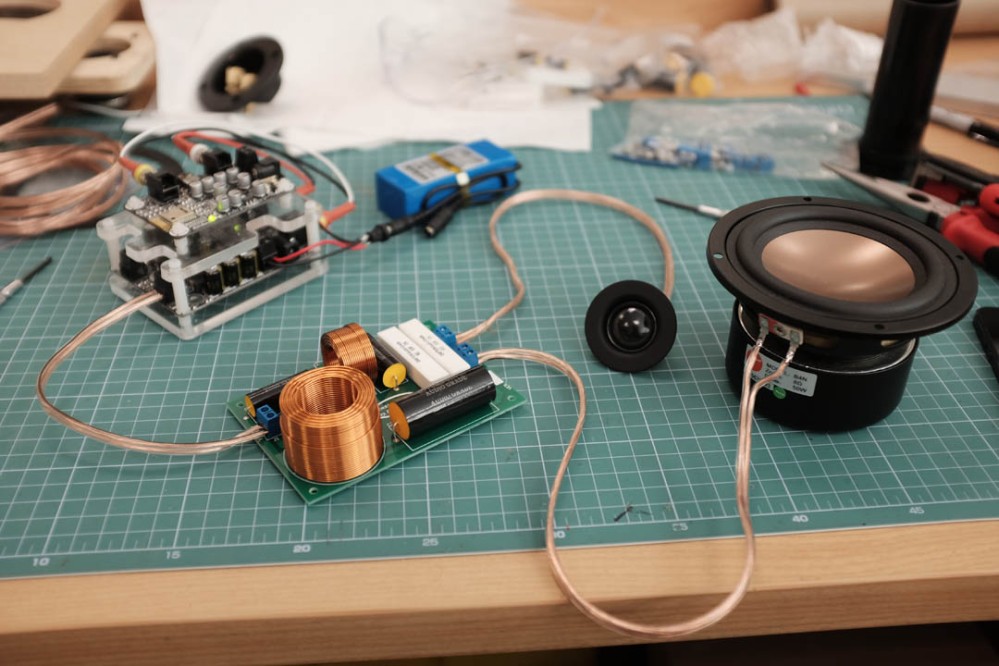
Everything was wired up and bench tested before installing into the cabinets. I used a Sure bluetooth board and amplifier setup powered by a 12V LiPo battery, these components are leftover from a previous project and I made a quick laser cut housing to keep things tidy. As it is very easy to turn the battery on and connect my phone via bluetooth, it has become my go-to bench testing setup.
One thing I noticed about the HiVi B4N drivers is that the outer surround was constructed of pressed steel and there is a thin adhesive foam gasket provided. It appeared to me that the gasket was too thin, when the driver was screwed into a recess the sharp edge of the surround would contact the wood before the gasket was compressed enough to form a tight seal. This may not have been such and issue and I did a quick search online and couldn’t see anyone else voicing this as a concern but I ended up laser cutting gaskets out of a similar but thicker material.
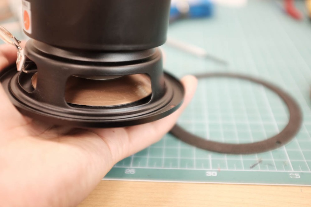
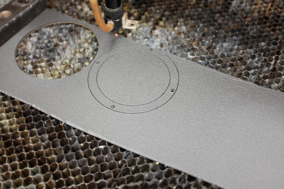
Here you can see the supplied gasket on the left which is roughly 2 mm thick and my gasket on the right which is roughly 3.4 mm thick.
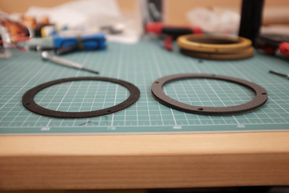
The gasket was stuck to the cabinet and it fit perfectly.
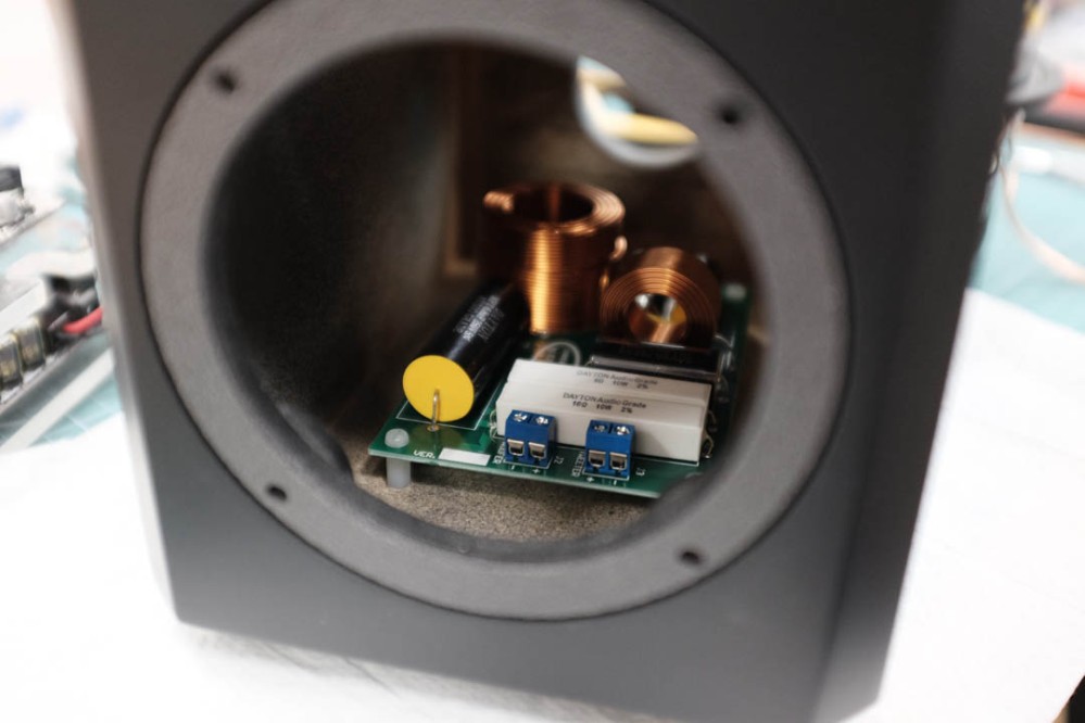
When designing the enclosure I had the forethought to machine some holes into the inside of the bottom panel, these holes were sized for a press fit with the plastic PCB standoffs which I planned to attach to the crossover boards.
This worked very well, the crossover standoffs could be pressed into the holes whilst attached to the PCB and seemed to be held down firmly.
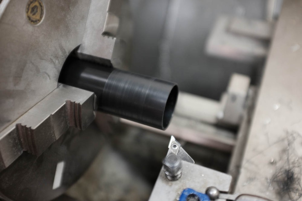
The specified port component was an adjustable unit consisting of a flanged piece and larger extension component. The idea is that the port length can be chosen and glued into place at the desired length. Unfortunately the extension component was slightly too large to fit through the holes I had machined in my cabinet. My solution was to machine roughly 1 mm from the diameter on a lathe.
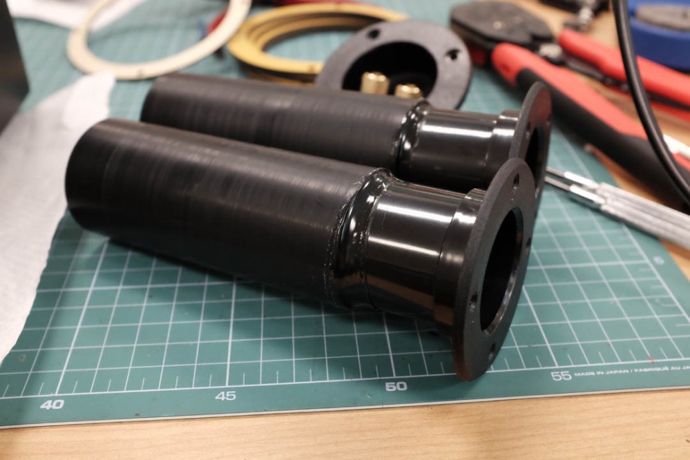
This image shows the port extension tubes machined down, hot-glued in place to result in a 6″ total port length and ready to install.
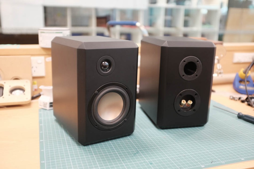
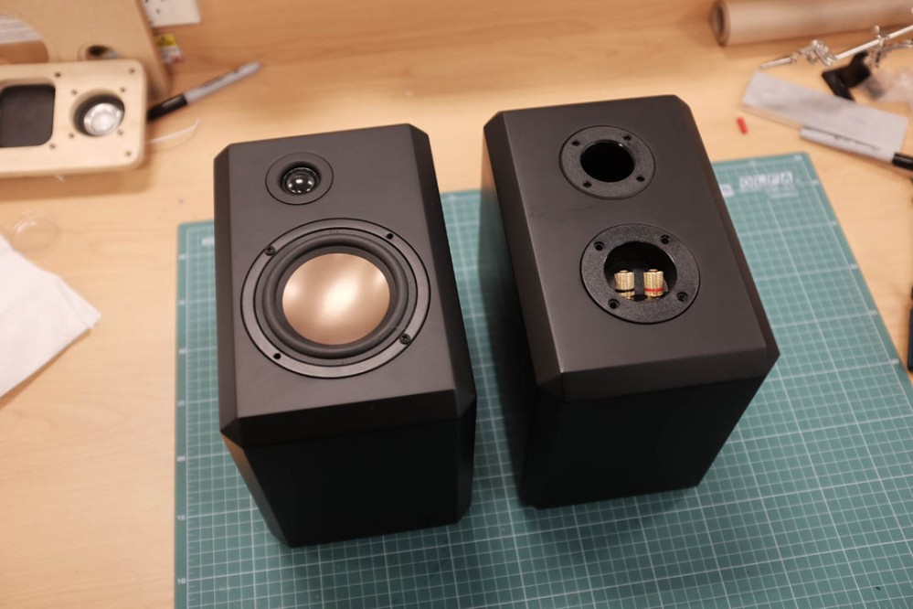
Completed speakers with all the componets installed and ready to test, excuse the greasy fingerprints.
Final Notes
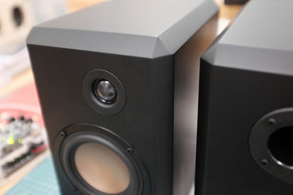
I am very happy with how these turned out, I think the matt finish looks great, especially with the heavily chamfered cabinets and in combination with the copper coloured driver cones. The only downside is that they mark and scratch quite easily and I haven’t found a way to restore them once scratching has occurred.
In terms of performance and sound quality, I am very impressed, especially at this price point, full credit goes to Paul Carmody for the design, they are certainly deserving of the praise I have seen given to them. They sound great, surprisingly big sound for a small speaker, everyone I have played these to have been thoroughly impressed.
As mentioned above, if you are located in Australia or New Zealand, I will be selling flat-pack cabinet kits for these speakers. Please see my ‘Overnight Sensations’ DIY flatpack kit blog post and email me via the contact page if you are interested in purchasing.
I am also looking at designing another set using birch plywood. I think the chamfers would give a nice effect of exposing the layered end grain of the wood. These would be finished with wax, oil or polyurethane which would also negate the need for so much sanding and painting!

Hey i was wondering if you could build the fronts for me but for a different driver and use plywood i can give you the lynk for the peerless drivers the tweeter i can do myself
LikeLike
Hi Dani, where are you located? I could do it but it depends on a few things.. Give me an email and we can talk about it. Cheers.
LikeLike
Amazing
LikeLike
Thanks.
LikeLike
Hi Mr. you are great
I like very much
LikeLike
Thank you.
LikeLike
Hello Jermy!
I was wondering if you have the CAD file for the gasket, or know where I can find on the web somewhere?
I´m trying out a design I´m building a 22 mm front baffel, and that willrequire a higher gasket. I´m going to use a 3d printer to make it and combine with rubber.
Regards
Johan Larsson
LikeLike
Hi Johan,
I believe the gasket is only to seal the edge of the driver. I think you can just adjust the recess that you cut into the front of the baffle to account for the extra thickness.
Please send me an email (address on “Contact” page) and I would be happy to send you a DXF file for the gasket.
Cheers,
Jeremy
LikeLike
Thanks for your answer Jeremy!
In this case, its not that design where I route the depth. I´m experimenting with a design where I use two separate mdf boards instead.
I will definitely send you an email. 🙂
Regards
/Johan
LikeLike
Hi Jeremy,
I’ve found with pressed steel speaker chassis that an epoxy mixed with talc to form a paste works well to fill in the hollow cavity of the surround. You then have a good base for a gasket and some marginal strength added to the otherwise flimsy pressing. I’ll be doing this on my OS’s. It might even suppress any vibrational tendancies. Good work on your enclosures too…
Regards, Martin
LikeLike
Hi Martin,
That sounds like good solution.
J
LikeLike
Hi, perhaps I am missing something, but it looks like you built, glued and painted the cabinet and after that you installed the crossover and the woofer+tweeter?
How did you manage to install the electronics into the sealed up box?
LikeLike
Yes the crossover board will fit through the woofer hole. So I installed that into the press fit holes in the bottom panel and then installed the woofer to close it up.
LikeLike
Hi Jeremy – Could you do something similar for the speedsters?
LikeLike
Hi Maralc, thanks for the comment, I’m sure I could but haven’t really had an opportunity to try. Cheers, Jeremy
LikeLike
Hello, these are the most beautiful ‘Overnight Sensations’ speakers I have ever seen. I use your metric dimensions.
I have a question. What should be the length of the bass reflex tube? I don’t know what length to buy or cut.
LikeLike
Hi Michael, thanks for your message. I used the standard port length recommended by Paul, which is 6″. Cheers, Jeremy
LikeLike
Hello, these are the most beautiful ‘Overnight Sensations’ speakers I have ever seen. I use your metric dimensions.
I have a question. What should be the length of the bass reflex tube? I don’t know what length to buy or cut.
LikeLike
Hello, this is the nicest Overnight Sensations I have ever seen. I borrowed your metric dimensions :). I have a question. How long should be the bass tube? I don’t know what length to buy or cut.
LikeLike