I purchased the Audiosector Gainclone LM3875 PCB + component kit about four years ago, it sat under my desk gathering dust until this year, when I finally decided to put it to use.
The Gainclone concept is based on the original Kimura-San/47Labs Gaincard design, which takes a “less-is-more” approach, low component count, extremely short signal path etc. at the heart of the amplifier is a pair of Texas Instruments LM3875 amplifier chips. More info on the Gaincard/Gainclone can be found here and here.
My goal was to build it into an integrated style amplifier with 3 switchable analog inputs and a volume control, similar to some of the examples I had seen on Peter’s website (Audiosector). I used a a TKD CP601 stereo attenuator as a volume control and a Lorlin CK rotary switch for the input selection.
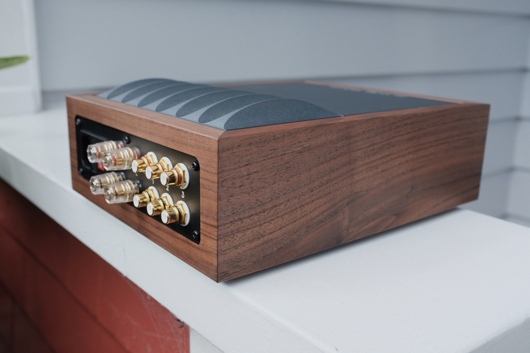
Below you can see my initial concept for the chassis design, black walnut chassis with grain-matched mitred corners and a custom machined aluminium heat-sink.


Although I purchased the “classic” version of the kit, I later regretted it and upgraded the components to the “premium” spec which consists of Kiwame metal film and Caddock MK-132 resistors.

This is the completed rectifier board.

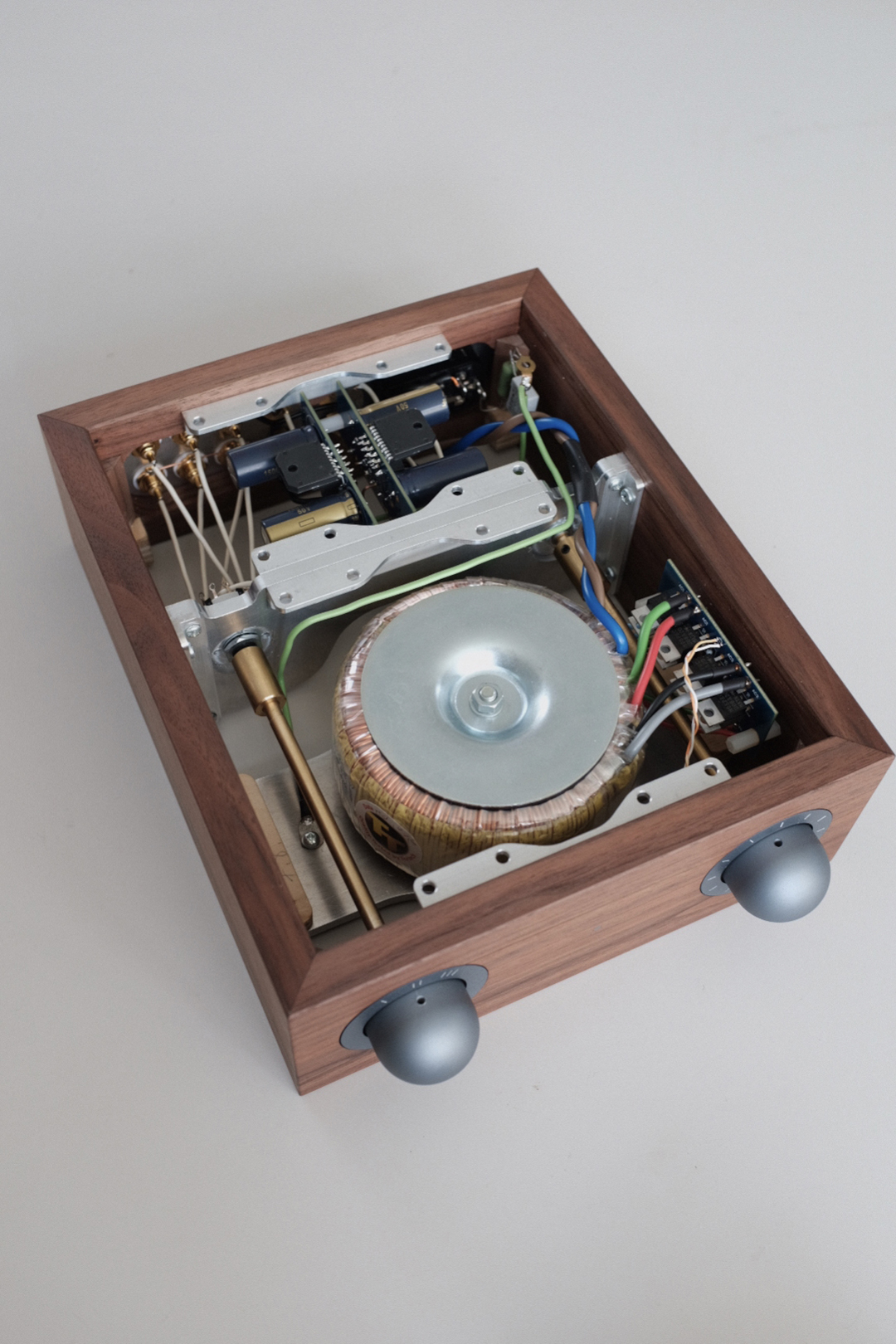
I sourced a custom wound toroidal transformer from TorTech in Australia, this is a 300VA transformer with a 240V input and 2x22V outputs.

The main components.

Testing the transformer outputs.

Part of this build was to test the capabilities of my home-built CNC router, in particular 3D surfacing in aluminium. I used the test-piece above to formulate and test various machining strategies. Once I had that worked out I moved on to the final component. Some footage of the machine in action can be found in the instagram posts below.


I ran roughing toolpaths perpendicular to each-other in order to remove as much material as possible before the ball-nose finishing pass. This resulted in a very interesting surface finish.

The finished heatsink, I was very happy with the surface finish.
For the chassis I began with this piece of black walnut.


I ran it through my thicknesser, which revealed the beautiful grain.


Sawn and planed to the right dimensions, all in one piece in order to preserve the grain. I wanted to have the grain running around three of the corners once everything was glued up. This meant there was no room for error or second chances when cutting the mitres.


Mitres were cut on the table-saw, this is not an ideal setup but I managed to get a decent outcome.

I love the look of the grain flowing around the corners.

Then I moved over to the CNC router to cut the pockets and other required details prior to glueing everything together.


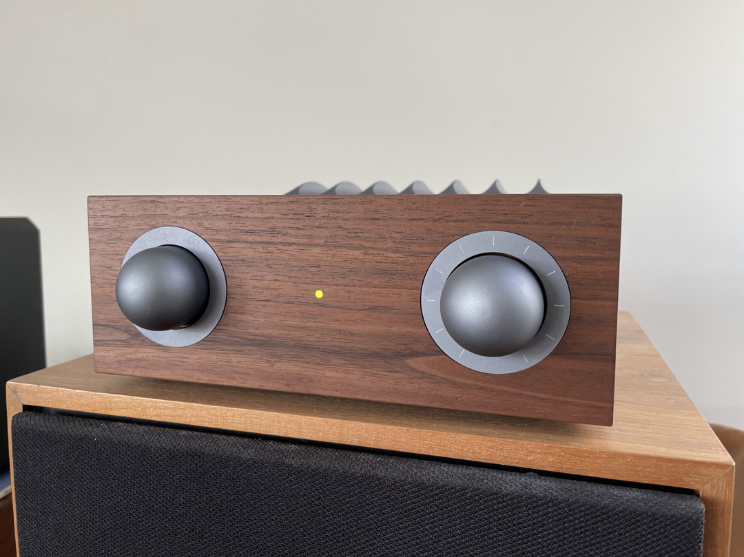
There’s a hole in the centre for a flush mount LED, I’m particularly happy with how this turned out, see the finished images at the end of this post.

Slots and locating features were machined into the inside of the side pieces of the chassis, rounded internal corners left by the CNC were carefully cleaned up by hand with a chisel.

Mitres were carefully trimmed and fine-tuned using my block plane.

One last look of the grain running across all of the sides. Tape was laid across the joints and the whole strip was flipped over.

Glue was applied to all the joins.


Completed chassis after a light sand.

This was my first time using Osmo’s Polyx-Oil and i’m really happy with the finish, it is easy to apply and dries very smooth and has a great waxy feel.


These brackets are screwed to the inside of the chassis and used to mount the various aluminium structural components. The are made from 12 x 12 mm aluminium angle.


Test fitting the internal structure components.

Power supply installed.

Flush-mounted power indicator LED in the centre front of the chassis.

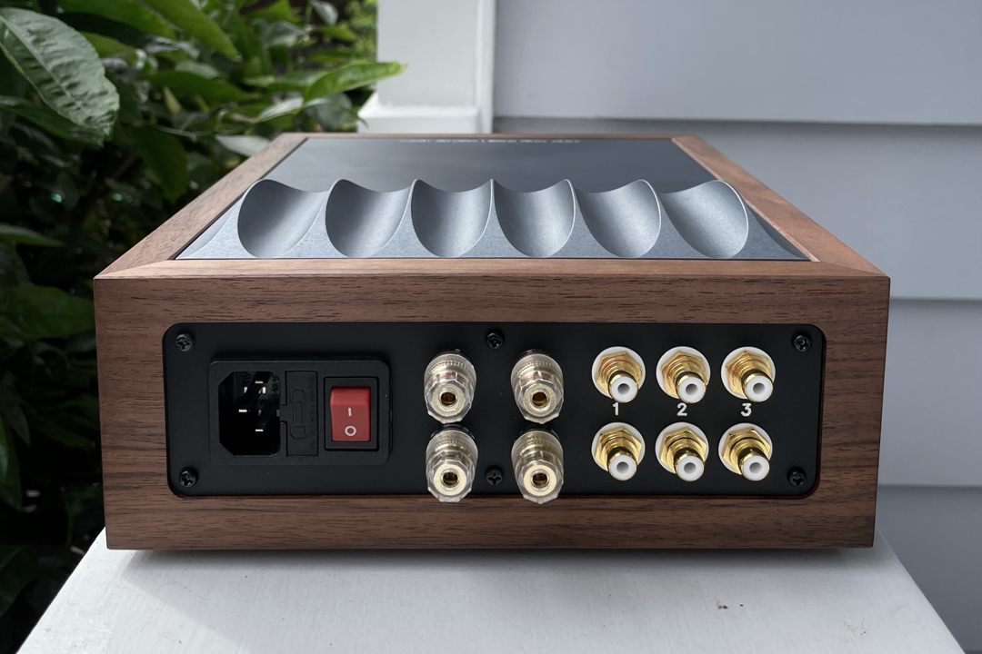
Rear panel components, CNC cut panel, fused IEC power socket, speaker biding posts, RCA sockets.

Test-fit in the chassis.

A quick coat of matte black paint.

CNC engraved lettering on the back panel.

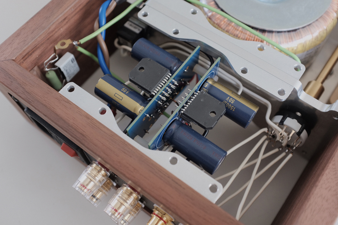
I mated the amplifier boards together using standoffs and installed a solid copper ground bus.

Test fitting various components into the chassis.

The majority of the internal wiring is solid core copper wire.
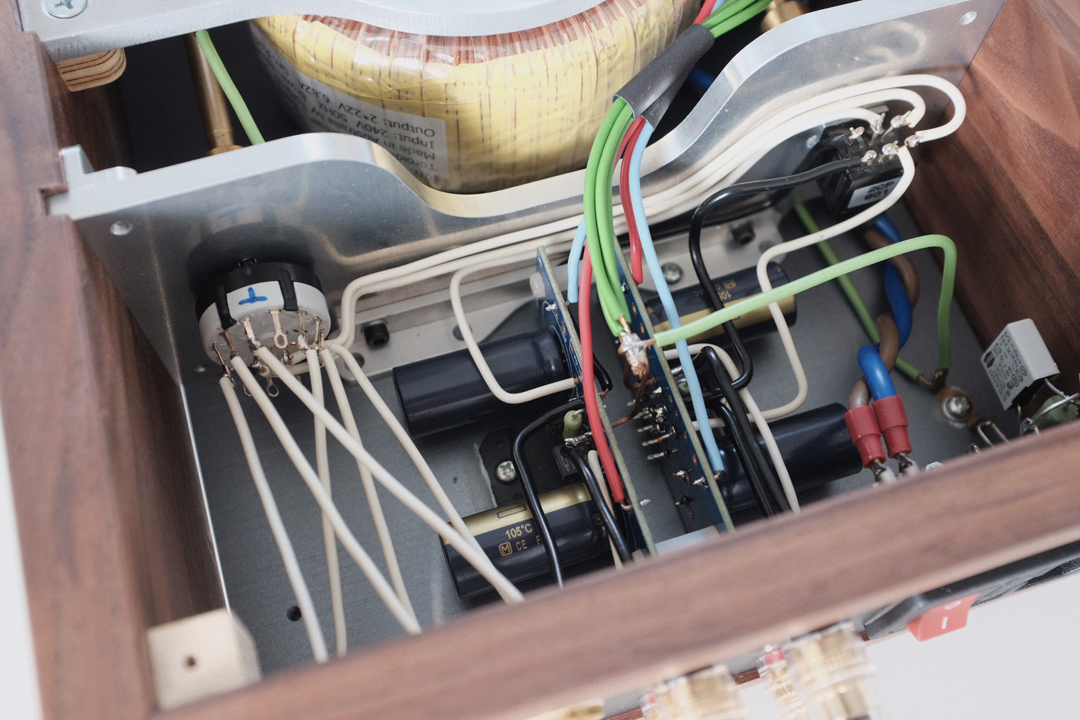
Here you can see the four PG+/PG- (green) wires coming from the rectifier board and connecting to the ground bus.


Voltage checks before first power-up.

A couple of small machining jobs to finish off with. I sourced some 12 mm and 6 mm brass rod to make the control extension shafts and couplings.

Shafts and couplings complete.

This is the underside of the heat-sink, drilling and tapping M3 threaded holes for mounting points, chip attachment points and grounding tag.


I accidentally drilled a hole in the wrong place and went through the part, this was very disappointing as I had to start from scratch and re-make the heat-sink. As part of the design I carefully placed the holes in thick parts of the component, but I unfortunately mis-calculated when it came to drilling them.


All the components complete, bead-blasted and ready for anodising.


I had the components anodised in “gun-metal” colour. There is some slight colour variation between parts but this is to be expected with this process, especially when using varying grades and thickness of material.
The top plate and selector/volume control rings were CNC engraved with markings and text.
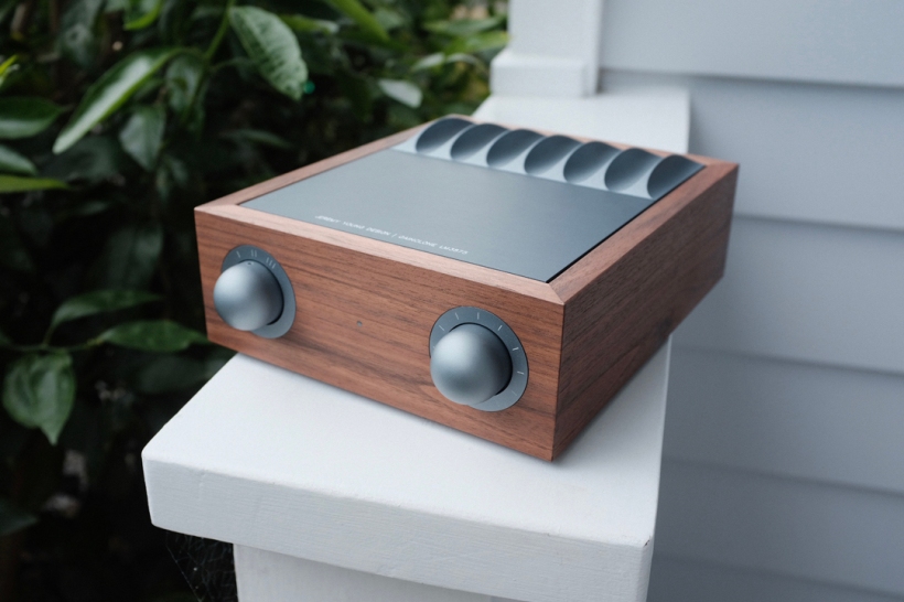
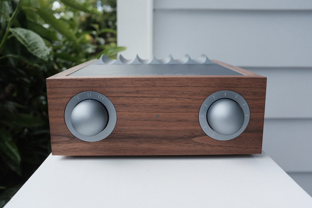
Some pictures of the final product are below, I am very happy with the result and I think it sounds great!
This isn’t the most powerful amp so efficient speakers seem to be ideal. It seems to perform well with the Spendor SP1 test speakers we have a sensitivity of 87dB/w.
The resident audiophile said with surprise, “wow, this is high-fidelity shit!” during the first listening test.


Beautiful piece of work, you are a perfectionist craftsman!
LikeLike
Thanks Aaron!
LikeLike
GIVE ME THEM KNOBS 😡
(btw Where did you get those knobs? Did you make them? If so amazing job! :D)
LikeLike
I ordered them off AliExpress.
LikeLike
Hi Dear: May I ask how is this amplifier? Because I use it myself, this amplifier is very beautifully designed and tasteful. I am from Hong Kong, thank you.
LikeLike
Amazing design and brilliant craftsmanship! Hats off.
LikeLike
That is exceptional, quite a masterpiece if I may say so! Your headphone amplifier also looks fabulous. Well done!
LikeLike
looks great. have you tried silver wiring?
LikeLike
Thanks. No I have not tried silver wire, this was only the second amp I’ve built.
LikeLike
Fantastic craftsmanship and really inspiring for all DIY hifi fans
LikeLike
Thanks Christo, I’m glad you enjoyed it.
LikeLike
Very nice Sound this gain clone amp and amazing design
LikeLike
Stunning! Makes me want to get a CNC…
LikeLike
jeremy
te felicito por tu capacidades .un artesano .
saludos desde chile
LikeLike
Hi, where can buy this amplifier and what price?thanks.
LikeLike