
This was to be a challenging project for me. It was my first time attempting hand cut joinery, and also my first high voltage tube amplifier build. Fortunately, for the electronic side of the project I had the guidance of my father who is very knowledgable when it comes to DIY tube and vintage audio gear. Visit his blog, Dark Lantern if this is of interest.
The tube amplifier circuit utilises 12AU7/ECC82 input & 6080 triodes and is output transformerless (OTL) and should pair nicely with the high input impedance of my Sennheiser HD6xx headphones. Input options are either switchable line level analogue or USB digital. As this amp will predominantly reside on my desk at work, the decision was made to integrate a high quality DAC as I have found the sound output of modern office PCs to be sub-optimal.
As usual with my projects, I like to mix traditional hand working techniques with modern manufacturing. I figured this was a great opportunity to try my hand at hand-cut dove tails whilst using my CNC router to cut some functional features.
Starting with the outer box, I sourced a couple of 150 x 25 mm planks of black walnut and it was milled down to the correct dimensions. The pith ran through the middle of this plank, so some portions were unusable but this wasn’t an issue as I ordered plenty of extra to use on future projects.

A block plane was used to get everything square, flat and true.


Initial layup / board orientation.

First dovetail cuts using a japenese style pull saw.

Waste was cut out using a coping saw and cleaned up with a chisel. At this point I realised I had made life hard for myself by laying out such narrow pins. Luckily I found a rusty old 2-3 mm wide chisel which would get the job done.

First dovetail joint ever! Not perfect, but it will be ok after some glue, and planing. It took me about 2 hours to complete the first joint, a lot longer than I expected.

After many hours, the hand cut joinery was complete, the front and rear panels were loaded into my CNC router for some machined features. Pockets and holes for the volume pot, headphone jack etc.


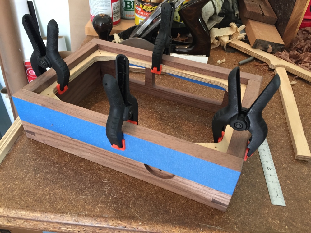
Glue up.

Planing faces and sides flush was extremely satisfying. I built this moxon vise especially for this project and i’m glad I went to the effort, it was very useful. There will be a future blog post on the vise build itself.
The box was finished with mineral oil and a microcrystalline wax finish.


I machined a plywood component to glue on into the outer box which the sub plate would be fixed to.

Carefully glueing in place, making sure there was an equal recess all the way around.
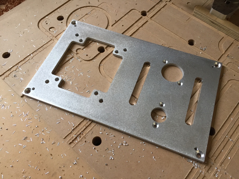
The sub-plate and rear panel were water-jet cut from 6 mm and 1.5 mm thick aluminium plate.

I later decided that the sub-plate needed some modifications, this was completed on my CNC router.
I gave these components a light sand with my orbital sander using 220 grit pads and painted with a matt black epoxy enamel.

The amp has been designed in such a way that most of the components are attached to the sub-plate and then a cosmetic top plate will be fitted to cover the holes and screws.
Below you can see the tube sockets and transformer have been mounted. The transformer is isolated using rubber grommets to dampen vibration.

The transformer is custom wound and an Alps “blue” RK27 100k log taper pot is fitted for volume control.

A wooden flexure clamp was designed to hold the three power capacitors. A mount was machined to mount the rectifier board under the transformer.

Rear panel was CNC engraved with input labels.

Test fitted into the box.

Power and signal circuit were both hard-wired with point-to-point construction. Considerable thought was put into obtaining the shortest audio signal path whilst retaining functionality and aesthetics.


Preliminary checks and measurements before powering up for the first time.

Initial sound tests are good.

The Khadas Tone Board was selected as the DAC because it is well priced, compact and the reviews were very promising. It was mounted using an aluminium bracket attached to the side of the box. Outputs wired to the input selector switch and a panel mount USB C extension used to provide digital connection on the rear panel. Note that the DAC will be mounted on shorter stand-offs when they arrive.


I utilised the workshop facilities at my work to machine the transformer cover from 6061-T6 aluminium on a Deckel 5-axis milling machine.


Lightly polished with abrasive pad to smooth out the marks left from machining.

Top plate, CNC routed from 1.5 mm aluminium sheet.

Transformer cover and top-plate were coated with Rustoleum Universal “Flat Soft Iron” spray paint.

I’m really happy with how this part turned out.

Some (a lot) images of the completed amp.


In conclusion, I am really happy with how this project turned out. I learnt a huge amount, new skills, concepts and I think it is one of the most satisfying things I have made so far.
It also sounds great paired with my Sennheiser HD6xx’s!

Excellent work sir.
LikeLike
Thanks!
LikeLike
It looks like a artwork. Good job!
LikeLike
Fine work! I’m sure it sounds incredible… Would you mind sharing the schematic for tube amp? I would like to build one for my DT990 Pro.. Thanks!
LikeLike
Love it, love everything about it. Amazing work. You should sell those xformer covers, they’d be a hit.
LikeLike
Thanks!
LikeLike
Very nice build. Beautiful! I also like your CNC router. I’m waiting for a smaller one to arrive tomorrow. So should be a lot of fun AND learning. I’m particularly interested in milling my front and rear panels for the enclosures I use for my electronic projects. However, after doing some reading, I may need a bigger/more powerful spindle motor.
LikeLike
Hi Rick, thanks for the comment. Which router are you getting? Milling thin aluminium panels doesn’t require too much power from the spindle.
LikeLike
Hi Jeremy, I got one of the ‘cheap Chinese’ 3018 CNC. It’s pretty basic and needs some calibration and a much higher RPM spindle motor for aluminum work I’m afraid. Still experimenting on softer material. It’s highest speed out-of-box is only 9000 rpm. Rick
LikeLike
That’s an awesome looking, and I’m sure, awesome sounding amp. I’m looking to build a HPA myself and was wondering where can I find the schematic? Great job!
LikeLike
Wow, this and your gainclone are very awesome. Your design asthetic is on point.
I have some hifi diy boards to make a lm3886 dual mono setup. I have never had great success of the volume control. I will try again with the same pot you have used.
LikeLike